Monday, 21 February 2011
Week 5 - Reminder that you hand in work at the end of Week 6!!!
Just a small reminder that you will be handing in work on the 4th March - three models that you will be using in your James Bond animation placed on a disc or memory stick along with a print out of your blog.
Lecture 5 - Camera modify panel

Within the modify panel, you can specify which lens you wish to use, there is a choice of nine lenses. The smaller the lens, eg 20 mm the wider angle you will see. The larger ie 85 the smaller angle you will see. Try toggling these amounts to see the difference.
Field of Depth
When you place an object in the distance in 3DS Max you can see the background object just as well and in focus as the forground object. This is not what happens in real life. If you look into the distance it is harder to focus then when looking at closer objects.
With Field of Depth you can make the background objects blurr to give a true to life representation.
Lecture 5 - Cameras - Setting up your camera

When you set up your scene, you have placed your camera/s, and changed your perspective view to camera view, you will see that the little symbols at the bottom of the interface have changed and are now specific to the camera. What is nice about these functions is that you can animate them.
Dolly camera - This allows the camera to move backward and forward without changing the lens length.
Field of View (FOV) changes the lens length without moving the camera.
Perspective view toggles different combinations of view.
Walk through, allows the use of the up, down, right and left arrows on the key board.
Orbit - The camera rotates
Pan - Rotates the target around the camera.
Lecture 5 - Cameras - Setting up your camera

To access and place a camera in your scene you need to go to Create > Cameras.
3DS Max offers two types of camera, Target and Free.
The most useful is the Target camera, as you can position the target onto the scene you wish the camera to look at.
Free cameras are better for animation, i.e. fly through animation where the camera can be aligned to a path.
You need to be careful as to which viewport you initially place your camera within, as they can be misaligned.
Target camera is click and dragged in the top viewport, so that it is to the ground.
Free cameras should be clicked into the front view.
In order to see the view that your camera is providing, click on 'perspective' in the perspective viewport>cameras>camera 01 and your perspective viewport will now react to any changes that you make to your scene with the camera.
Tuesday, 15 February 2011
Lectrure 4 - Skylight system
In the create panel > lights > standard > Skylight. Click to add skylight in the front viewport.
With the light highlighted go to the modify panel and under the render panel click shadows.
Now render your scene - a lovely matt finish!
Lecture 4 - Gamma Correction
If you use photoshop you will probably know about the 'levels' adjustment that is offered there. This allows you to make your photograph darker or lighter, in other words it adjusts the Gamma of the image. Gamma correction is built into products such as computers and televisions and it is set at 2.2. Mac computers are set to 1.8.
The Gamma setting is built in to compress the information produced in shadow areas (light and shade). The Mental Ray rendered used for Raytracing has to know the correct Gamma, otherwise rendering can take longer than it needs to. Also the with the correct Gamma the colour of bitmapped shapes is richer and more saturated. Gamma does not affect ordinary colour, only the colour of the bitmaps in your materials as they appear applied to geometry.
You therefore need to turn the Gamma on:
Turning Gamma on
Go to the customise drop down, and click on preferences > Tab - Gamma and LUT (look up table).
Check enable Gamma,
Also under bitmap files - Output and input 2.2
Enable Affect colour Sections
Affecct Material Editor.
Toggle the UI setting in the render panel to see preference box where you can change settings for test renders which will decrease render time.
Under Limit trace depth keep Max reflections at 2 and Max refractions at 4.
Lecture 4 - Understanding Raytracing - Chrome & Glass materials
To produce a chrome material
Open the material editor, select a slot. In the Maps rollout, click on reflection > in the maps rollout click Raytrace. Drag the material to the object, and render.

To produce a glass material
Open the material editor, select a slot, click on background so that your material shows up. Make sure that you have your diffuse colour as black. Go to the Maps rollout, click on refraction and choose Raytrace. Click and drag to the object and render.

Monday, 14 February 2011
Lecture 4 - Lighting
Max has two default lights in
the viewports which enable the user to see their models in a basically lit environment. As
soon as you start to add yo
ur own lighting, that default changes, and Max updates t
he view to whatever lighting
that you specifiy.

Make a small scene, click and drag a plane in the perspective viewport and place assorted standard and extended
primitives on that plane, so that you can test out the di
fferent lights.
Go to the Create panel, and
click on the small lighting
symbol. Where you can see Photometric, click on the side
arrow and select Standard.
In the Front viewport click and drag a target spot.
In order to see your lighting update it is a good idea to change one of the viewport
s to Perspective view - Active
Shade.
Target Spotlights are very useful for mood lighting, free
target spots can be used for car headlamps, streetlamps
etc. A spotlight illuminates an area within a cone, similar to a
stage light. Target Spotlights point at a target that you aim at
, whereas few spotlights are targetless, so they can be
moved easily. You can align a target light to a path and
animate it if you wanted to.
With your target spotlight highlighted, go to the mo
dify panel, and it will reveal a target spotlight rollout.
Under general parameter
s, you can change the light to either an Omni light or
Directional light. An Omni light
radiates light in all directions and is ideal for general sunlight, or an overhead light in a roo
m, the light radiates from the
one source. Directional lights use a cone of illumination and the sides of the cone are
parallel rather than radiating from a single source like spotlights.
You will also notice that you can add shadows. Just check the box next to shadow and
miraculously you will get
shadows within your scene.

Here you can specify different shadow types using different
rendering techniques.
In the next box you will find Intensity/Colour Attenuation.
Here you can change the intesity of the light by changing the Multiplier spinner, and if you click on the colour square you
can change the colour of the light. Here I have changed the colour of the light to green, and
have added an extra target spot to illuminate the scene even more so that you can see the changes.
You can also change the attenution. You can change your spotlight from a round
stagelight to a square light in the spotlight parameters box.
In Advanced effects you can add a map to your spotlight. Check the projector map box
and click on the map box to add either a proceedural map or one of your own. I have added a map of fence wire to
mine and here is the effect it provides.

Omni lights and Directional lights have the same rollouts and parameters, so it is a good idea to play with these to see what sort of lighting effects that you can produce.
Monday, 7 February 2011
Lecture 3 - Making a leaf
This tutorial can be found on the VLE under Module Documents. You will also find the relevant map of a leaf to download.
Lecture 3 - Producing a High Shine metallic material

- In the Create panel go to Extended primitives. Click and drag a torus knot in the perspective viewport.
- Open the Material Editor. Pick an Anastropic shader as this is ideal for metal materials. Check on the diffuse button and change the colour to a dark blue. Make sure that you have a high specular level approx 60 and a high anastrophy approx 80.
- Navigate to the maps rollout further down the panel, Click on Reflection > None and click on Material Library. In the Material library there should be some environmental maps - pick a scene such as Hong Kong. This will now add the Hong Kong image to the reflective map channel.
- Drag the material from the slot to the torus knot.
Lecture 3 - Producing a Multi Sub-Object material

This technique is great when you have a poly model that requires different
materials - such as a character wearing clothes.
- Click and drag a teapot into the perspective viewport.
- Convert the teapot to an editable poly.
- In the modify panel, check element.
- Scroll down to polygon properties to Material ID
- Click on the teapot spout and allocate ID 1
- Click on the lid and allocate ID 2
- Click on the belly of the teapot and allocate ID 3
- Click on the handle and allocate ID 4
- Come out of editable poly.
- Open the material editor.
- Click on Standard to pull up the proceedural map menu > choose Multi/sub object material > OK.
- You now have 10 material slots. You add materials or maps to the first four slots. Click on Material#standard and either add a map or make your own material. You then see these materials in the sample slot.
- Click and drag the sample slot material to the teapot and the different materials are automatically assigned to the different elements of the teapot.

Lecture 3 - Making your own materials

In order to make your own materials to import into 3DS
Max, you need to use Photoshop.
Make a new file, approx 3cm x 3cm. Using the brush, make a random pattern within the f
ile. Save as a bitmap.
In 3DS Max, click on the Material Editor. Click on a
slot and got to the diffuse slot. Next to the slot is a small box. Click on this and it revea
ls the material editor. At the top of the material editor is Bitmap. Click on Bitmap, and a
dialogue box appears to allow you to find the image you made in Photoshop. The image w
ill appear in the material slot. Click and drag it to your object.

Lecture 3 - Shaders
In order to start making materials you have to chose the relevent shader to make that material. Shaders are similar to the different types of background that you would chose to paint on, for instance, watercolour paper for watercolour paints, sugar paper for pastels, board for acrylics, or canvas for oil paints. You need to use the correct shader in order to produce the right balance of refraction/reflection to make your chosen material.
Anastropic
The anastropic shader is ideal for metal materials, because it changes the shape of the specular from round to elongated via the anastrophy spinner. You can also change the direction of the shine. It works very well for hair where the shaft of the hair catches the light.
Blinn
This is the standard Max default - A basic shader which can be used for most materials, it has a no anastrophy.
Metal
This was in use until the Anastropic shader was introduced, it is more simple in the way it works, there is a dimple in the specular graph, which means that the shader is useful for dull metal materials such as brushed stainless steel.
Muli-layer
This is very good for metalic objects, particularly cars, as it has two layers of specularity. You can also change the colours of the specular layer to add subtle tones.
Orin-Nayer-Blinn
This is much softer in tone than Blinn and produces a very soft feel to the material. It is ideal for organic materials such as skin, velvet, as it slightly absorbs light.
Phong
This is one of the original shaders and is not really used anymore. Gives a plastic feel to a material.
Strauss
This is good for plastic, or can be used for metal, but there are not a lot of parametres and is not utilised much.
Translucent
This is a fun shader - and can be used to produce psychodelic influences on the material, glowing effects etc. It offers translucency, and opacity plus filter colour.
Wednesday, 2 February 2011
Lecture 2 - Making a linear array
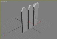
Make a shape like a piece of picket fencing in the perspective viewport. Make sure this is highlighted.
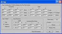
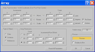 Go to Tools > Array and this opens an array dialogue box.
Make sure that the Preview button is checked
In array dimensions, check 2D, and in the Count select how many copies of the fence post you require. Then click on the X spinner. You can now see the fence post being cloned. Take the X spinner up to 25.
Now check 3D, and choosing the Y spinner, you will see the set of fence posts being cloned, take the spinner again up to 25.
Lecture 2 - Loft


Modelling a coat hanger using Loft
In the front viewport, using the line spline tool, draw out the shape of a coat hanger.
Also in the front viewport, click and drag a small circle (spline)
Go to Creat > Compound Objects > Loft.
Make sure that the coat hanger spline is highlighted, and then in the Loft properties box, click on get shape, and then click on the circle.
You now have a complete coat hanger.
Lecture 2 - Boolean and Pro-Boolean

Create a large flat box.
Now create a letter from Spline text. Turn the spline into an editable poly. Extrude the letter so that it is deeper than the box and cap the end.Place the letter in the middle of the box so that it intersects it.
Go to Create > Compound objects > Boolean
In the Boolean parameters it will tell you that the box is operand A. Click the Pick Operand B button and choose the letter as Operand B. In the properties dialogue you with to subtract B from A.
Now you have an letter shaped Boolean through your box.
If you have more than one shape that you wish to boolean, use the pro-boolean tool which asks you to keep picking operand B until all the shapes are removed.
Lecture 2 - Use of splines and lathe modelling
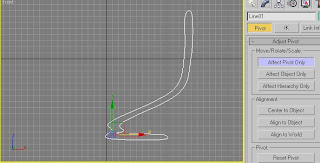

Lathing
Go to the create panel > shapesUsing the line tool, set Initial type and Drag type to smooth – this will provide you with a curved line.
Click and drag your shape in the Front viewport.
When you have produced your shape, you need to change the pivot point from the centre of the shape to the base of the shape so that the lathe modifier rotates around the base of the bowl. Navigate to the modify panel/list, pick the lathe modifier.
This will automatically lathe around the Y axis, but you can change this if needs be in the lathe properties panel.
Subscribe to:
Posts (Atom)